Thermal cameras are highly effective tools for maintaining HVAC chillers, allowing technicians to detect potential problems early, optimize system performance, and prevent costly breakdowns. By identifying heat imbalances, refrigerant flow issues, electrical faults, and mechanical wear, thermal imaging helps ensure that chillers are operating efficiently and reliably. Here’s how to effectively use a thermal imaging camera for HVAC chiller maintenance.
- Why Use an Infrared IR Camera for Chiller Maintenance?
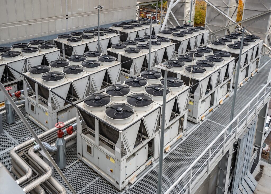
Chillers are critical components in HVAC systems, responsible for cooling large commercial and industrial spaces. They work by removing heat from the circulating water and rejecting it into the atmosphere via condensers. Over time, various components of chillers can experience inefficiencies, and a thermal imaging camera allows you to:
- Detect temperature imbalances: Spot temperature variations in the refrigerant and water circuits.
- Identify refrigerant issues: Detect leaks or blockages in the refrigerant lines.
- Monitor electrical components: Identify electrical problems such as loose connections, overloaded circuits, or failing components.
- Inspect mechanical wear: Spot wear and overheating in key mechanical parts like motors and compressors.
- Ensure heat exchange efficiency: Monitor the performance of condenser and evaporator coils.
- Key Areas to Inspect in Chiller Systems Using Thermal Imaging
- Compressor
The compressor is the most critical part of the chiller system, responsible for compressing the refrigerant gas and enabling the cooling process. Any inefficiency here can affect the entire system.
- Check for overheating: Use a thermal imaging camera to scan the compressor for any abnormal hot spots. Overheating could indicate problems such as worn bearings, lubrication issues, or refrigerant flow problems.
- Evaluate temperature consistency: The surface of the compressor should show an even temperature profile. Variations in heat patterns may signal internal damage or inefficiencies.
- Condenser Coils
The condenser coils are where the refrigerant releases heat to the outside environment. Efficient heat rejection is crucial for maintaining cooling capacity.
- Check for uniform heat distribution: Use thermal imaging to scan the condenser coils and ensure that heat is being dissipated evenly. Hot spots could indicate issues such as dirt build-up, restricted airflow, or a failing fan.
- Inspect fan motors: The fans responsible for moving air over the condenser coils should show a normal operating temperature. Hot spots on the fan motors or uneven temperature distribution could indicate mechanical wear or electrical issues.
- Evaporator Coils
Evaporator coils are where the refrigerant absorbs heat from the circulating water, cooling it down. Maintaining efficient heat transfer is key to the chiller’s performance.
- Scan for temperature uniformity: Thermal imaging can help you ensure that the evaporator coils are cooling evenly. Cold spots in some areas and warm spots in others could indicate refrigerant distribution issues, ice build-up, or restricted water flow.
- Detect icing: Icing on evaporator coils reduces their ability to absorb heat. Use the thermal camera to detect cold spots where ice may be forming and interfering with cooling efficiency.
- Refrigerant Lines
Refrigerant lines carry the refrigerant between the evaporator, compressor, and condenser. Leaks or blockages in these lines can severely impact chiller performance.
- Detect refrigerant leaks: Cold spots along refrigerant lines may indicate a refrigerant leak. These leaks cause inefficiencies and can lead to compressor damage if left untreated.
- Identify blockages: If the thermal camera shows abnormal temperature changes in the refrigerant lines, it may suggest a blockage that is restricting refrigerant flow and reducing system performance.
- Pumps and Motors
Chillers rely on pumps and motors to circulate water and refrigerant through the system.
- Inspect for overheating: Use thermal imaging to scan pumps and motors for hot spots that might indicate overworking, poor lubrication, or mechanical wear.
- Check for uneven temperature distribution: Uneven heating in motors or pumps may indicate misalignment or excessive friction, both of which can lead to premature failure.
- Electrical Panels and Components
Chillers have various electrical components that control the system’s operation, including circuit boards, power supplies, and connections.
- Scan for hot spots in electrical panels: Use thermal imaging to check for loose electrical connections, overloaded circuits, or failing components. Hot spots in these areas can lead to electrical faults or fire hazards if not addressed.
- Inspect starters and relays: Overheating in starters or relays could signal electrical imbalances or wiring issues. Thermal imaging helps you spot these problems early.
- Steps for Using a Heat Detector Camera for Chiller Maintenance
- Preparation
- Ensure the system is operating under normal conditions: For accurate thermal imaging, the chiller should be running at its normal load. This ensures that the system’s components are working as they would under typical operating conditions, revealing any performance issues.
- Set the thermal camera to the appropriate range: Make sure your thermal imaging camera is set to the correct temperature range, typically between -20°C to 150°C for HVAC applications.
- Performing the Thermal Inspection
- Start with the compressor: Scan the compressor for any unusual hot spots or temperature variations. Look for signs of wear, electrical faults, or refrigerant flow problems.
- Move to the condenser coils: Use the thermal camera to check for uniform heat rejection across the condenser coils. Pay attention to any areas where heat is not being dissipated effectively.
- Inspect the evaporator coils: Look for consistent cooling across the evaporator coils. Cold spots may indicate ice build-up or refrigerant distribution problems.
- Examine refrigerant lines: Scan the refrigerant lines for cold spots that could indicate leaks or blockages.
- Check pumps and motors: Use thermal imaging to inspect pumps and motors for overheating or uneven temperature distribution, which may indicate mechanical issues.
- Scan electrical components: Inspect electrical panels, relays, and starters for overheating that may signal loose connections or overloading.
- Analyzing the Thermal Images
- Look for hot and cold spots: Identify any temperature anomalies that deviate from normal operating conditions. Hot spots in electrical components or motors often signal inefficiency, wear, or impending failure, while cold spots on refrigerant lines may indicate leaks or blockages.
- Compare with baseline data: If you have previous thermal images or baseline data for the system, compare the current results to spot any changes or trends.
- Document findings: Save the thermal images and record any temperature anomalies for future comparison and reporting.
- Common Problems Detected with a Thermal Imager
- Compressor overheating: Hot spots on the compressor can indicate mechanical wear, refrigerant issues, or electrical faults.
- Condenser coil inefficiency: Uneven heat distribution on the condenser coils may suggest restricted airflow, dirty coils, or fan motor issues.
- Evaporator coil icing: Cold spots on the evaporator coils often signal ice build-up, which reduces the system’s ability to cool effectively.
- Refrigerant leaks or blockages: Cold spots along refrigerant lines suggest leaks, while temperature drops or spikes along the lines could indicate blockages.
- Electrical faults: Hot spots in electrical panels or components signal loose connections, overloaded circuits, or potential electrical failures.
- Benefits of Using a High Resolution Thermal Camera for Chiller Maintenance
- Early detection of issues: Thermal imaging helps identify problems like refrigerant leaks, compressor wear, or electrical faults before they lead to system failure.
- Preventive maintenance: Regular thermal inspections enable you to spot potential issues early, allowing for repairs before major breakdowns occur, reducing costly downtime.
- Energy efficiency: By identifying inefficiencies such as poor heat dissipation or airflow blockages, thermal imaging can help optimize the system’s performance and reduce energy consumption.
- Improved safety: Detecting hot spots in electrical components or mechanical parts can prevent electrical fires or overheating that might pose safety risks.
- Best Practices for Thermal Imaging in Chiller Maintenance
- Conduct regular inspections: Incorporate thermal imaging into routine maintenance schedules to track the condition of critical components over time.
- Monitor high-risk areas: Pay special attention to compressors, evaporator and condenser coils, and electrical components, as these are common failure points.
- Keep records: Document thermal images and temperature readings to create a maintenance history. Comparing current images with past results helps identify trends and predict future issues.
- Use in conjunction with other diagnostics: While thermal imaging is a powerful tool, combine it with other diagnostic methods such as pressure readings, electrical tests, and visual inspections for a comprehensive chiller maintenance plan.
Conclusion
Thermal imaging is a crucial tool in HVAC chiller maintenance, helping technicians spot issues like refrigerant leaks, electrical faults, and inefficient heat transfer before they escalate into costly repairs or system failures. Regular thermal inspections ensure that chillers operate efficiently, maintain cooling capacity, and prevent breakdowns, making them an integral part of any preventive maintenance program.